
Matrix Multiplication in FPGA
Motivation
Matrix multiplication is a common operation in many applications, such as machine learning and image process. It also involves packing of input and output data, and sequential logic design. Therefore, it is a good practice for beginner to implement a matrix multiplication module in FPGA.
The whole project can be found on Github here.
Project outline
- Using Python to realize a proof of concept. Verilog is very different from regular coding language. There’s no console and everything you are dealing with is waveform and thus making it hard to debug. It’s a common practice to use Python or C to verify the algorithm before implementing it in Verilog in order to maximize the efficiency.
- Implementing the module in Verilog. This is the main part of the project. The module is implemented in System Verilog, which is a superset of Verilog. The main reason using System Verilog here is that it supports packing of output. With this ability, we could support “resizable” matrix multiplication. User could specify the size of input matrices and the module will automatically scale according to the given size.
- Write a simple test bench in Verilog to verify the module is working as expected. This step aims to locate the obvious syntax or logic error in the module.Many simple bugs could arise just by compiling the file.
- Use Python and cocotb to test extensively using randomized input. This could detect potential logical flaws in the design.
Proof of concept - Python
Here is the python code. Since Verilog doesn’t support 2D array very well, we map the input to a 1D array and do the operation according to index.
def matrix_mul(A, B, Col1, Row1, Row2):
    C = Col1*Row2 * [0]
    for i in range(Col1):
        for j in range(Row1):
            for k in range(Row2):
                C[i*Row2+k] += A[i*Row1+j] * B[j*Row2+k]
    return C
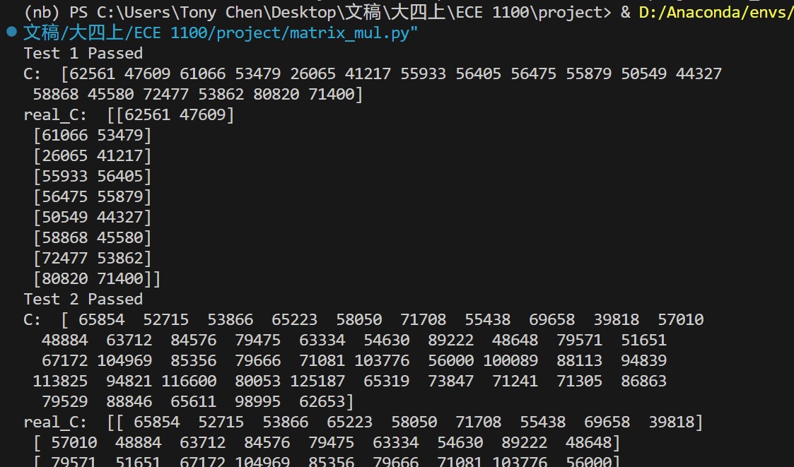
Test it and it works as expected.
Verilog implementation
`timescale 1ns / 1ps
module matrix_multiply #(
    parameter Col1 = 2,
    parameter Row1 = 2,
    parameter Row2 = 2
) (
    input [15:0] a[Col1*Row1-1:0],
    input [15:0] b[Row1*Row2-1:0],
    output logic [15:0] c[Col1*Row2-1:0]
);


  integer i, j, k;
  always @(*) begin
    // initialize c
    for(i = 0; i < Col1*Row2; i=i+1) begin
      c[i] = 0;
    end
    // calculate matrix multiplication
    for (i = 0; i < Col1; i=i+1) begin
      for (j = 0; j < Row1; j=j+1) begin
        for (k = 0; k < Row2; k=k+1) begin
          c[i*Row2+k] = c[i*Row2+k] + a[i*Row1+j] * b[j*Row2+k];
        end
      end
    end
  end
endmodule
It’s almost the exact duplication of the python code logic. Let’s do a simple test bench.
module matrix_multiply_tb ();
  reg [15:0] a_in[0:3];
  reg [15:0] b_in[0:3];
  wire [15:0] c_out[0:3];
  matrix_multiply dut (.a(a_in), .b(b_in), .c(c_out));
  initial begin
    a_in[0] = 1;
    a_in[1] = 2;
    a_in[2] = 3;
    a_in[3] = 4;
    b_in[0] = 1;
    b_in[1] = 2;
    b_in[2] = 3;
    b_in[3] = 4;
    #3 $stop;
  end
endmodule
The $stop here tells the simulator to stop. Otherwise, it will run forever and crush when you run out of memory. Also, we need to noted that testbench data is not synthesizable on real Hardware.
Here’s the wave form of it. We use ModelSim to simulate the design and it works as expected. 
Automated testing with cocotb
cocotb is a Python framework for verifying digital logic in simulators and FPGA. It’s a great tool for automated testing. 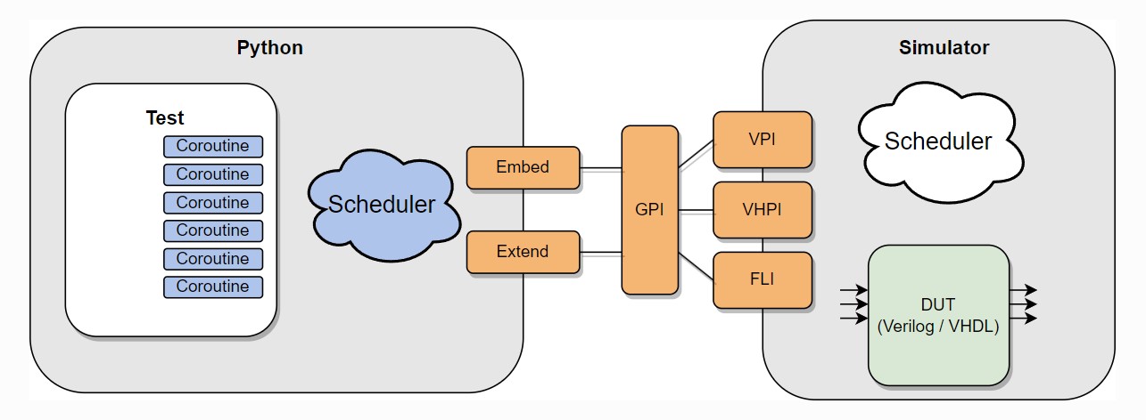 Source: https://docs.cocotb.org/en/stable/
Here’s the Python code for testing.
import os
import sys
from pathlib import Path

import cocotb
from cocotb.triggers import Timer
from cocotb.binary import BinaryValue
from cocotb.runner import get_runner

import numpy as np

@cocotb.test()
async def test_matrix_multiply_randint(dut):
    # cocotb returns binary
    c1 = 2
    r1 = 3
    r2 = 2
    for i in range(3):
        A = np.random.randint(1,200, size =(c1,r1))
        B = np.random.randint(1,200, size =(r1,r2))
        A_flat = A.flatten()
        B_flat = B.flatten()
        for ii in range(len(A_flat)):
            # dut.a[].value <=   assign is not working
            dut.a[len(A_flat) - ii - 1] <= A_flat[ii].item() # from MS to LS
        for ii in range(len(B_flat)):
            dut.b[len(B_flat) - ii - 1] <= B_flat[ii].item()

        await Timer(5, units='ns')

        real_C = np.matmul(A, B)
        test_C_flat = [int(j) for j in dut.c.value]
        test_C = np.array(test_C_flat).reshape(c1, r2)
        status = "Failed"
        if(np.array_equal(real_C, test_C)):
            status = "Passed"
        print("========================================================")
        print("Test %d %s" % (i+1, status) )
        print("Test A: \n", A)
        print("Test B: \n", B)
        print("test C: \n", test_C)
        print("real C: \n", real_C)

def test_adder_runner():
    """Simulate the adder example using the Python runner.

    This file can be run directly or via pytest discovery.
    """
    hdl_toplevel_lang = os.getenv("HDL_TOPLEVEL_LANG", "verilog")
    sim = os.getenv("SIM", "icarus")
    proj_path = Path(__file__).resolve().parent

    verilog_sources = [proj_path /  "matrix_multiply.sv"]

    # equivalent to setting the PYTHONPATH environment variable
    sys.path.append(str(proj_path / "tests"))

    runner = get_runner(sim)
    runner.build(
        verilog_sources=verilog_sources,
        hdl_toplevel="matrix_multiply",
        always=True,
        build_args=["-P", "matrix_multiply.Col1=2", "-P", "matrix_multiply.Row1=3", "-P", "matrix_multiply.Row2=2"]
    )
    runner.test(hdl_toplevel="matrix_multiply", test_module="test_matrix_multiply")


if __name__ == "__main__":
    test_adder_runner()


# reference:  https://github.com/cocotb/cocotb/blob/d19464474ad2b990732f062359a2c144bc6e3fb8/examples/matrix_multiplier/tests/test_matrix_multiplier.py
With the example of cocotb official repo, we could construct such a test bench fully in Python. All we need to do is to set the environment such as icarus here and the path of the verilog file matrix_multiply.sv. dut in the test function is the module we are testing and we could access and modify its value with . operator. To log the result, we could simply print it out. We could also rise error with assert statement, so that we get cocotb would report the run as failed. Here is a screenshot of the result. 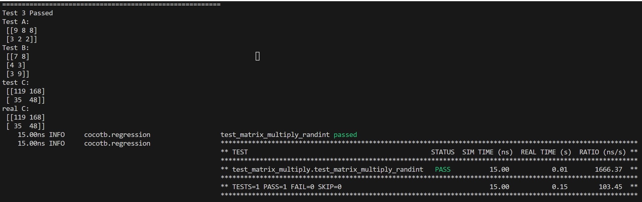
Final Check on Quartus
Writing a Verilog code that works directly in simulation tools such as Icrarus Verilog or ModelSim are not enough. There are many other things we need to keep an eye on. For example, the initial block usually cannot be synthesized. We need to use reset instead. Also, the testbench data is not synthesizable. We need to use a real clock and real data. Therefore, it’s necessary to check the design on Quartus to make sure it works on real hardware. The Quartus would take far more time to compile and make sure the design meets all kinds of real-world constraints.
It’s simple to check your design in Quartus. Just create a new project and create a new Verilog file and paste your code in it. Set the code as top-level module and then just click Start Compilation. Here is screenshot of the result.  One can also check the RTL view of the design.
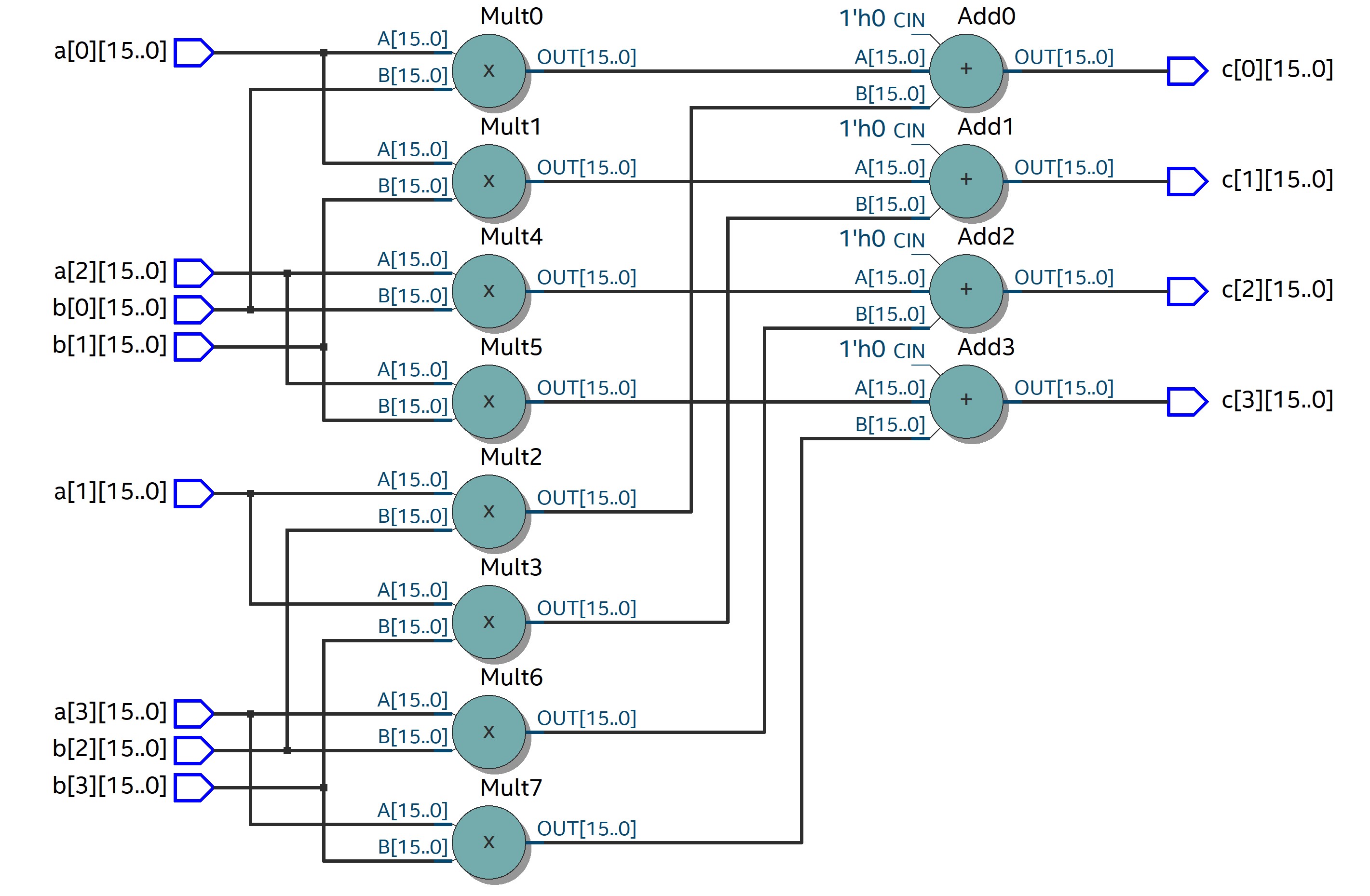
Conclusion
In this project, I implemented a naive matrix multiplication module in Verilog. I also used cocotb to automate the testing process. This project is a good practice for beginner to get familiar with Verilog and cocotb. For the next step of this project, more optimization for the design can be done such as pipelining and parallelization. Also, the module can be extended to support more features such as different data type.